2022-07-19 18:11:52 3805
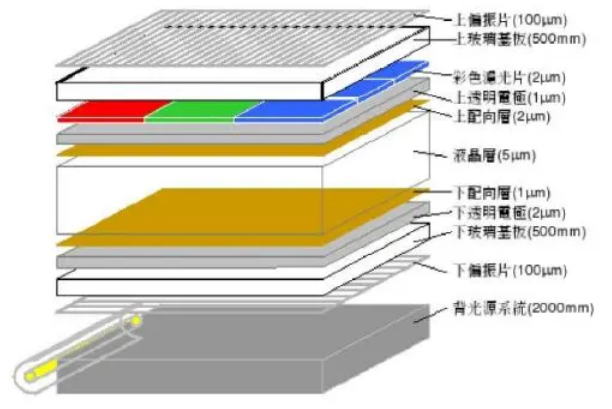
Sectional view of the internal structure of the TFT liquid crystal screen. It can be seen from the figure that the liquid crystal screen is composed of a light diffuser, a storage capacitor, a row and column electrode, a glass bottom plate, a polarizing glass plate, a TFT, a transparent display electrode, a transparent common electrode, and a color filter. The liquid crystal is located between the transparent display electrode and the transparent common electrode in FIG. 6 , and the functions of each component will be introduced one by one below.
1. Light diffuser: After the light emitted by the backlight passes through the light diffuser, it can be evenly distributed to each pixel;
2. Storage capacitor: its capacity is about 0.5PF, and its two poles are connected to the transparent display electrode/transparent common electrode. Since the capacity between the transparent display electrode and the transparent common electrode is about 0.1PF, it cannot maintain the charged voltage When the screen is updated next time (for example, when the refresh rate is 60HZ, the holding time is about 16MS), so it needs to be maintained by a storage capacitor;
3. TFT: Thin-film transistor, is a switching device that determines whether the liquid crystal is charged (the thin-film transistor only plays the role of on or off, when the thin-film transistor is on, the voltage is output from its source to charge the liquid crystal and the storage capacitor, and the charging voltage is The level is determined by the LCD drive circuit);
4. Row electrode: the scan electrode, also called the gate bus, is connected to the gate of the thin film transistor in each sub-pixel;
5. Column electrode: The signal electrode, also known as the drain bus, is connected to the drain of the thin film transistor in each sub-pixel;
6. Glass bottom plate: for isolation;
7. Polarizing glass plate: the polarizing plate, the inner polarizing glass plate 1 has a horizontal opening, and the outer polarizing glass plate 2 has a vertical opening;
8. Transparent display electrode: connected to the source of each thin film transistor, and forms a charging electrode together with the transparent common electrode to charge the liquid crystal in each sub-pixel;
9. Color filter: Also known as color filter, it is a piece of glass composed of many transistors. To display a color image on the LCD screen, a 10. color is usually added between the transparent common electrode and the polarizing glass plate 2. After the light penetrates the liquid crystal layer, it passes through the color filter. Since the color filter is arranged in three colors of red, green and blue in the horizontal direction, the three colors of R, G and B are alternately arranged. The color is divided into three independent points, each point corresponds to a sub-pixel, and the adjacent three points of R, G, and B have different grayscale changes and form a pixel at the same time. Many pixels with different grayscale changes are composed of space The principle of additive color mixing allows us to see a colorful picture.

